This page is made special to try show how I create
what I call a "Shadow mesh" to sort of make a shadow of
the roof down on the walls on any gmax structure where I find it
useful to use a shadow. This technique is very useful where the
texture used for walls is not very suitable for "painted
shadow" where the shadow it self is sort of painted into the
texture. When using a "tile able" brick texture for
instance. Or a wood texture where you need to tile in both height
and width. Normally a wooden siding can be used with "painted
shadows" if it is just tiled sideways, but not always.
So, to help out a friend I've been trying to learn this too I
have made this page. It is quit heavy on graphic as I've tried to
use as much screenshots as possible, so please bear with me as the
graphic loads. :-)
This page deals with an already made model, so if you need help
making the basic, be aware it will not be found in here. :-) I've
used gmax version 1.2 in this pictures. Sorry for the "baby
steps" below, but I figured let me really try to make it as
easy as possible. :-) Step
1 to 18 is about mesh editing, while the texturing is from step
19 and onward.
1 - This
is the start of this exercise, for this one I've used a
small mine structure of mine (the Mountain Boy), but in your
end if would of course be the mesh you want to use. :-)
-> The red marking is marking off a tool I like to have
on the screen in that area as I don't have to move the mouse
all the way down to middle bottom where you also find the
"X, Y, Z" boxes to put in the coordinates of the
stuff you need. To bring this box on the screen, press F12
or find it under Tools on the gray upper
toolbar. I started by
marking the roof as you can see in all the four view ports -
this is because the roof is already made and instead of
spending time fitting a new box I just reuse the one making
up the roof.
2 - Next step is to Make Sure
you have the "Y" in upper
middle (#1) pressed down Before
doing anything else. Then, hold down Shift and
start dragging the marked roof from step 1 down (or up if
you want that). It don't matter how far you drag it down.
-> Those "X, Y, Z, XY"
markings up there limits the movement to that axis in the
"viewport" window you happen to work in. Quite
nice to use sometimes when copying or moving things. As soon as
you start dragging it down, you will get the "Clone
Options" window up (#2),
be sure it is marked with "Copy" as you want it to
be independent and not in any way inter react with the roof
it self. [Had you marked in as "Instance" it
would he made a clone where a change in either the roof or
this new part would been showing up in both - very useful
for making windows/doors/beams/posts - but not here. :-)] Also, be
smart and make it a new name (#3)
instead of the default name which is the name of the part
you copy/clone with a number 01 added. Click OK
when your finished.
3 - This reduced size picture is just
showing that as Step 3 I went back to mark the roof and
found it's "Z" info which I took a note of (either
in head, paper or a calculator)
4 - I then used the "Z" info from
Step 3 and took out in this case 0,3048 meter (1 foot) and
used that as the "Z" info for the shadow mesh.
This is the reason why it didn't matter how far down (or up)
you drag the copy of the roof, as it was to be put in place
here anyway. LOL [This
is also the step where I should have done a few "clean
ups" and taken out bottom and top of the box making up
this part, but, I didn't, so that will be shown later (Step
14 - 18). But,
if you are smarter then me, do it here... :-) Also, you
should make sure the sides are fitted together (Step
16), again, I
forgot, so it will be shown later.]
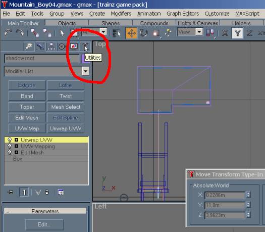
5a - Now, move you mouse toward the upper
left corner - see the hammer?
- where I have the red circle above. When hovering mouse
above it, it reads "Utilities" -
please click on it.
-> This is due to the fact that the mesh/object making up
the shadow part is already holding a texture as the roof I
made it from have a texture added and edited. By going to
Utilities you will find a tool to remove this texture - see
next picture.
5b - Find "UVW Remove" (marked
in red), Make Sure the shadow
mesh is the marked one and not the roof or anything else! Then, select
the "Materials" button (marked
in red) and push it down.
-> This will remove the material from the mesh and return
it back to it's original color as assigned by gmax (or you,
when you made the box) The "Set Grey" checkbox
will as far as I know just make the mesh appear gray instead
of another color.
6 - Next I needed to remove the
"mapping" [the part telling gmax how the
texture is to look/behave on the mesh] of the shadow
mesh. I did that by right-clicking on the top
"modifier" (marked in red)
and choose Delete. In my case that was the
"Unwrap UVW" modifier. Second, I
needed to remove the second modifier too, which in my case
was the "UVW Map".
-> This step and the above is done so I don't have any
mapping info left to maybe screw things up later. This step
and the above is also classified as "Nice to Know"
info! LOL
7 - Next step is to make the shadow mesh a slightly
smaller size then the roof mesh. As I have made the roof
from two boxes "attached" together I can't use the
way I normally do it. [That is to move to mouse to the
bottom of the "stack" where it reads
"Box" below the "Edit Mesh" modifier as
I always keep it there and never use the "convert to
edit mesh" but instead uses the modifier with the same
name.
-> This gives me an extra undo button so to speak as when
I delete the "edit mesh" modifier I get back the
original box. :-) It also gives me a possibility to go back
and change a few things on the original box and have it show
up - or mess it up which happen if I add segments and still
have the "edit mesh" modifier above.] As I
above have used two attached boxes I can't use the trick
with resizing the box a little and instead I need to work
with the Vertexes them self - hence the red
markings above. I've chosen
them, then I drag the mouse around all the Vertexes on one
side. With them marked I move them to the right (in that
case, other time it might be to the left, up, or down...
LOL) by reading the "X" info (or Y/Z if other
directions is needed) either at bottom of screen or as I
use, that middle window and reduce it (as in my case) with 1
cm so it will be just a tiny bit on the inside of the roof. This is done
then on all the sides. There should be no problem leaving it
at the size of the roof, but I do prefer to have it a tiny bit
on the inside, what ever you prefer, the principle should be
the same. :-)
8 - Next in line after making the shadow
mesh a little bit smaller then the roof is to size it up to
the roof. There should be two ways to do that, one would be
to go back to the box and make it as much higher as you put
it below the roof in step 4 above. But as I explained above,
having used two attached boxes that is no option for me so I
need to do it the other way. Which is by
raising the "Z" value of the "upper"
vertexes on the shadow mesh it self. For me that involves
reusing the "Z" values from the roof itself,
hence the above picture shows what happens when I mark the
roof (the little red raised part
in upper left). Then, the rest of the picture tells the
story what happens when I mark the "Edit Mesh"
modifier and opens on the Vertex part. That middle
Warning window pops up [and I personally prefer to
never turn it off so I never ever mark the little checkbox
in lower left of that window.] -> The window is a warning window to let you know
that things you do in here might change things in the above
stack, and sometimes it is a good thing to have this warning
show up as I might have clicked in here without noticing it
and not wanting it and hence I might stop my self from doing
a disaster to a mesh. :-) Click Yes
and the windows go away, and you can then mark the lower
vertex on the roofs and get it's "Z" value. Either
just transfer that right over to the shadow mesh by copying
the info, then leave the roof mesh by clicking on "Edit
Mesh" and then select the shadow mesh, "Edit
Mesh", Vertex and paste it in, or write it down for all
the needed lower heights before moving to the next step. :-)
9 - This screen shows how I have selected
the shadow mesh, and is about to paste in the info into the
Z value box marked in red. [I often use the
"mark, copy, leave, select, paste, leave, copy, leave,
select, paste method" my self. LOL] Do that
with all the upper Vertexes of the shadow mesh and you soon
end up with picture below - where all the sides are now
going up to the roof. (Or at least almost to the roof, to be
totally honest, due to the "narrowing" in of the
shadow by that 1cm the outer edges of the shadow mesh will
not be all the way up to the roof so if your real picky
beware. LOL)
10 - This step is the one that makes the
shadow mesh look more like a shadow then a box around/under
the roof. :-) Notice that
red marking above in the picture? Remember from above
what they do? [As I
now will work with the "Left viewport window" I
need to move the Vertexes sideways (X in this window) so I
press this button down to make sure I only move it left or
right.] You are now
left with two ways to do this part. One is to use the method
in last sentence and just move them into the wall by eye,
the other is the way I normally do, by using the
corresponding X, Y (or Z) info for the walls! :-) Easy,
right? LOL
11 - In this screen there is a lot of info.
:-) First, look at my marked red
handpainted "square", see that little
reddish dot in lower right of that square? That is the
Vertex now at same "Y" value as the wall it self -
but see how it is below the lines marking up the slope of
the shadow mesh. The reddish
inset at the right of that square shows how it looks after I
by marking the "Along the Y" (red circle marking
up at top) dragged that vertex so it by my eye look flushed
along the sloped line. I then use
that same "Z" value on the other side of the roof
after pulling in the lower vertexes to the wall the same
value as I used on the front side [I used a calculator
with memory and just added/removed the values as needed in
the X and Y value boxes at middle of the screen.] When you
have completed that on all the straight sides you now have a
sloped downwards into the wall kind of box - time to move on
to the next step. :-)
12 - Take a wild guess what I do
here... LOL Yes, I decided that if you haven't
already saved by now, do it NOW!
LOL [I
have gmax set up to add a number behind every save so I end
up with a lot of versions unless I use "Save As and
overwrite the file I am at now, which happens quite often
until I have done any major and would like to have the
option to go back if I mess up, then I use just save as
here.]
13 - With the Save done, let us move on to
do the inward motion on the short sides where the
"slopes" are. I first didn't want to show it with
a picture as it is the same as step 11 above, but then I
decided, let me have a picture in here anyway. LOL As my roof
overhangs the same on all sides it's easy to just remove/add
that overhang to the X value and voila, instantly inward
going box! :-)
-> The inset in red is to show how I got from a textured
look to the wireframe look, by right-clicking the name of
the window (in this case, "Front"). More of the
basic I'm pretty sure you know, but guess it don't hurt to
show it. :-)
14 - This is the step I
mention in Step 4 way up there above, this should have been
done a long time ago but I totally forgot it until I was
setting up the "inwards" on the vertexes. You need to
remove the top and bottom parts as they are of no use what
so ever and will only add unneeded polygons. So, I raised it
by clicking up the Z value enough to clear the roof with a
meter or two. By clicking the Z value up you can just click
it down and it will fit where it was while dragging it up
makes it harder to get it back to the same position.
15 - I've put in this step in case you don't
know/remember how to take out polygons. :-) Follow the
numbers, mark the item, go to "Edit Mesh" (#1)
and open/find the part called "Polygon", click on
one of the parts you want to remove and it will turn red (#2)
and just press the Delete button on your keyboard. You might
want to use the tools at circle 3 (#3)
to aid in finding/getting to the polygons you want to
remove. One of those tools move the content of the window
around, the other helps you in rotating it. Best done
in the Perspective (or as I have it set up as, User) window.
16 - This is trying to
give you a hint about the - in my eyes - important part of
"merging" this 4 vertexes into just 2 vertexes as
the insert shows have happen. You do that
by using the "Y" and "Z" values from the
vertexes you have in correct placement (the lower/closest to
you vertex) and reuses them as the values for the vertexes
that needs to be moved. [It's quite simple copy/paste
and shouldn't take long at all]
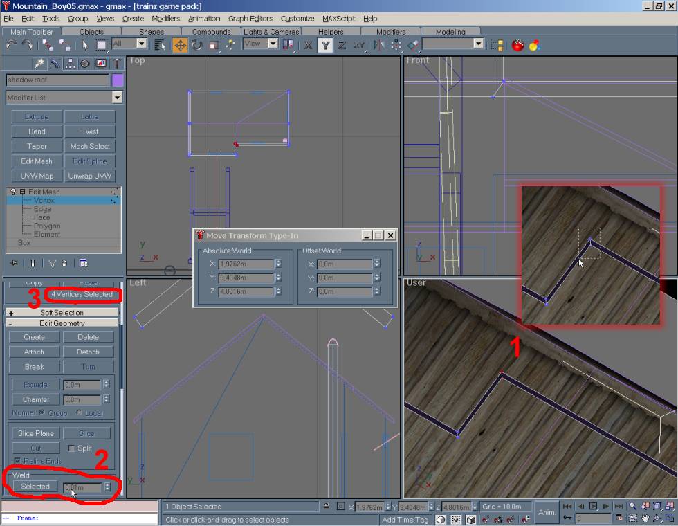
17 - This is the step trying to explain the
Weld command. :-) First, I
have once more used an inlay (red frame) to show several
steps - that one shows how I marked the vertexes, by
dragging my mouse around them. (#1) Then, I used
went back to the lower left part where I moved the toolbar
down so I got the window you see here (#2
& 3) and the "Weld command is visible at the
bottom. The number
2 marking is important as this tells gmax which
vertexes in how large area around the marked ones it should
weld/clue together. If you have a not so high mesh make sure
the number here is lower then that height! Or it will weld
them all and you end up with 1 vertex while we here want 2
of them. The number
3 marking is just to show how gmax tells you how many
vertexes there are in the selection. After Weld is applied
this will change from 4 to 2 and all is well. Remember to
push that "Selected" button in number
2 - or nothing will happen! If you want to push it
again, feel free, but you only get up a window telling you
that there are no vertexes to weld. :-) Also
remember to set the shadow mesh back to the height it used
to be by lower the number in the "Z" value box
back to where it was.
18 - Time for another save, this time I used
Save As to overwrite the same file as not much really have
happen except I've tweaked the mesh quite much. You also see
how the shadow mesh is back under the roof and has all the
"inwards" done - well done! LOL
End Mesh Editing Part, Now Texturing...
(Finally) LOL
19 - It's on to the
part where I really hate this new version of gmax as I don't
really liked the new way of assigning/doing textures with...
:-( You see the red
circle on the screen - this is the first place you
need to click.
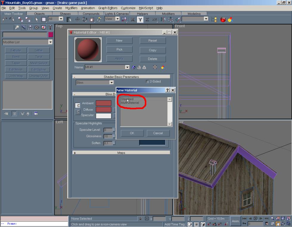
20 - That will bring up this window - which
for me as a devoted user of gmax v1.1 is not at all what I'm
used to... But, it didn't need a science degree to
understand that what we want is the "Standard"
choice for a new material/texture. Either
double-click it or mark it and click OK.
21 - This cut out of the whole
window is what shows up when you choose the New Material
thing in above step. The arrows
are just a way to try show the steps I would take when
setting up a new texture using this v1.2 way. [As this
is a totally new way for me I might not do it the best way
but at least I manage to do what I wanted so I guess it
can't be that bad. :-)] The part
with the red circle around is a part I think is very
important, as this is the place you give your material a
meaningful name so it is easier later to know what it is by
just looking at the name instead of a cryptic Mtl#xx... :-) When you
have decided on a name it is time to move down to the part
that says "Maps" and expand it so you can set up
the new textures to use with this material. [At least
that was what I figured out, might be wrong but it seemed
logical so I hope I don't do any "bad learning
away" thing here.]
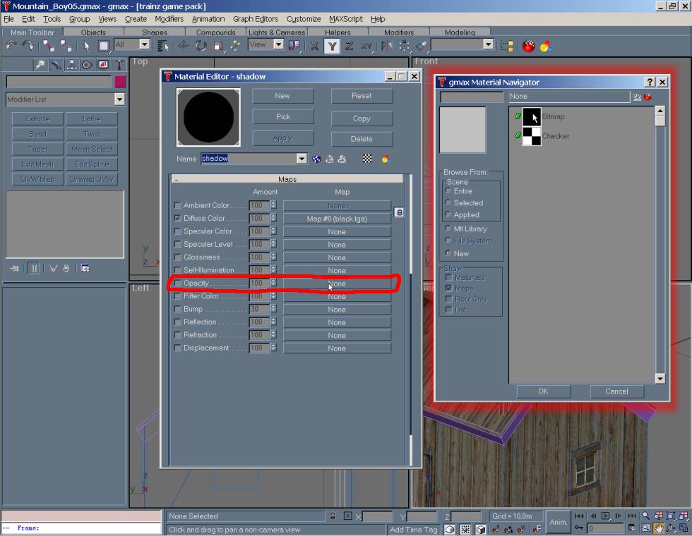
22 - When you expand the "Maps"
you will get this window, where I have marked
out in red what I believe is the normal setup for use
of a texture as the name "Diffuse Color" sort of
reminds me of a similar/same name in v1.1 and which is the
part where I assign a texture to a material in gmax. [Personally
I don't understand why they to have all this names such as
Diffuse, Maps, Material, Textures when it all is sort of
textures, but I guess there is a reason behind it all.] I had to
click on the part that says "None" to move on to
the next picture below.
23 - When this window
pops up I'm pretty sure you need to double-click on the part
called "Bitmap" You might also be able to just
mark it and then click on OK, but as double-click work, why
not use it? :-)
-> I have no idea/clue what that part called
"Checker" means - it might be a faster way to add
a transparency/alpha/Opacity part to a texture, but I never
tested it so feel free to try it and all that. :-) [I
double-clicked and it gave me the next window.]
24 - I've marked the
two files we need for the shadow, but for this
"Diffuse" thing we only need that "black.tga"
file (or what ever you call it) mark it, and then Open (on
my Laptop is says "Åpne" or "Avbryt, but it
means Open or Cancel) your self out of that window. :-)
25 - Moving on we find our self back here,
and for some unknown reason to me it said another name in
the "Name" window marked in
red above. I had to use the small arrow button to
bring it back up again. Before that I think the window
looked different, but for some reason I couldn't find it in
my screenshot files so I might remember wrong.
26 - Then I do the same again as in Step
23 and Step 24 above, except that
you this time choose the "black.bmp" file which
holds the needed grayscale info to make the tga file into a
file that sort of bleeds away from black to nothing.
-> If you had a tga file with a alpha layer in it -
making it into a 32bit and not a 24 bit as the above file is
- you would instead have chosen that tga file again for the
Opacity thing. This essential makes the material in gmax
partly see-through! :-) This might
also be a good time to make a new save (with a
new name in case things go wrong).
27 - This screens tells a lot - some if it
is that I really didn't knew what I was doing as the texture
didn't show up... Number
1 is what I pressed to be able to select the mesh
part I wanted textured. Number
2 is the part I select to get textured. Number
3 is where I press "Apply" so the texture
shows up (ha, I thought at least, but as you see, #2
is still gray...) Red
circle and ! is
where I later learned I should have also pressed, this need
to be down before textures shows up - so be Aware! Also, make
sure that the correct texture/map/material is selected in
the "Name" window as it somehow seems to default
to a map/texture I didn't make... [So,
as you might have understood, I'm not that smart, as I did a
few errors, and have decided not to show them to you and
instead move on to next successful screenshots that really
shows what I wanted. The non shown pics are just screens of
mapping like the ones coming up below, but with no change in
the window showing the model it self...]
28 - This is how step 27 should have looked
like, but I chose to include step 27 still as it sort of
shows one of the errors one can easy do I think. Number
1 shows how the Apply button have made the shadow
mesh become black. Number
2 indicates that I have chosen the right
texture/map/material And Pressed Down that all important
little thing at direct right of the Name selection part. Number
3 shows how I have 2 textures set up in this one
material [hey, maybe that is why they uses names like
that, to try avoid confusing which would really happen if it
all was called just textures, hmm, I think I'm smart... LOL] Number
4 is the adding of the "mapping part", for
this part we chose the "Unwrap UVW" option.
-> The mapping part is what tells gmax, TOE, Trainz how
the texture is applied to the sides making up the visible
model, and there are two ways to do that. One is the
"Unwrap UVW" which gives you as much control over
location/look of the texture as I think is possible, and the
other is the "UVW Map" thing which is very useful
for parts that needs a texture that you know the dimension
on, as in, how large area the texture would have covered at
it been on a real thing.
Like, a brick texture, the bricks are so and so in size, and
the texture shows for instance 10,5 bricks - all you need to
do is then figure out how large that area that texture
covers and use that as an info in the "UVW Map"
options. Real simple and easy! [But,
for this project, we use option number 1 (Unwrap UVW), as I need the
control, and it really don't need any tiling.]
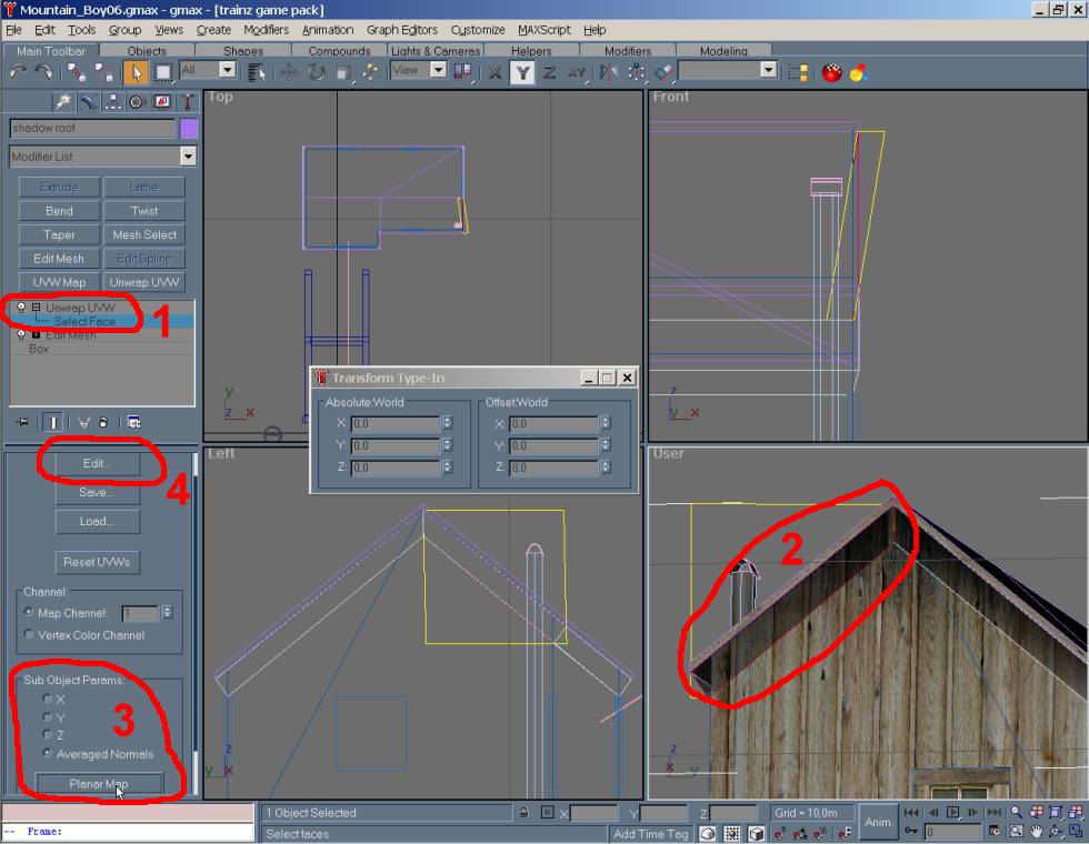
29 - Now, this is where some of the fun
begins - to see it right onto the mesh. :-) Number
1, open up the "Unwrap UVW" by clicking
that little plus sign and then click on "Select
Face" Number
2, then click on one of the sides you want to edit
and have it show up as marked as you can see in the partly
red frame and the yellow thing. Number
3, You might need to scroll down the tools a little,
but find that "Planar Map" button and press it [I
just love that button, it makes life so much easier for me!] Number
4, This is the button you next click, it will open up
a new window where you will fit the texture so it looks the
way it should look. For this exercise we don't need it to
tile at all so it is quit simple work. [Important Note!-
When you use the "move" or-
When you use the "move" or/and the
"rotate" tools to move the view in the work window
(those tools is found in lower right corner of gmax - looks
like a hand and a compass things with arrows pointing out) -
you might need to click back on the word "Unwrap
UVW" in #1 before
"Select Face" again is useful to select a part.
This is sort of a way to refresh it so you get the pick tool
back so to speak. Sorry I have no way to show it, other then this
words.]
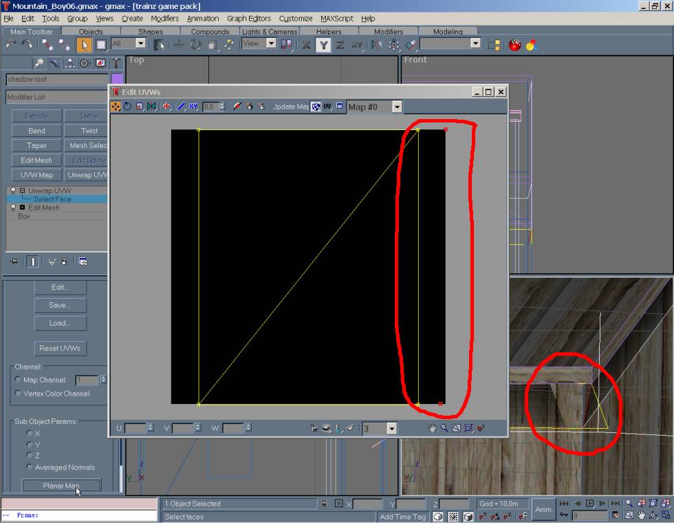
30 - This is the window that opens up, and
if you look in lower left you see the three letters U (#3),
V (#4), W - all with a room for
putting in something.
-> This is height (V - #4)
and width (U - #3) and I think depth
(W) but not real sure about that one. They operate on the
basic that "0" is the left most border of the
texture, and the bottom of the texture while "1"
is the right most and upper border of the texture. If you
write "2" in any of the two windows for two of the
small points it will tile the texture so it is sort of twice
as large. Quit simple, right? LOL Number
1, this little window here can be used to isolate
just the part that you used "Planer Map" on in
last step. Scroll through list until you see 4 dots that are
red, like in #2 frame. Number
2, is the marking of the face/polygon/part you chose
in last step. You need to take one red dots on each side of
the texture (for instance "upper upper right", and
"upper lower left") and mark only. You do that by
click somewhere in this window, so the red dots disappears,
then click first one dot and while holding down ctrl on
keyboard you click the other dot so you are left with two
dots. See pic below where the lower pair is marked. Number
3 and Number 4 is
mention above.
31 - As mention above, just that I've chosen
the lower ones as you can see. The two needed dots are
marked, the fact that I have a third marked is not a problem
as they all will end up on same place and the reason I have
that square already is the fact that I already have mapped a
few sides. :-) You see how
I have written "0" in the "V" window (#4
above), and as soon as I now press Enter on keyboard those
marked red dots will drop down to that lower part of the
texture.
32 - This is just a continue of the above,
you see how #2 is still showing
4 so I'm at the same "page" so to speak. Number 1a
and 1b belongs together, I've
already have done the two dots still in that
"slope" on above picture and marked them and put
them up to value 1 in the "V" window. Here I have
then marked the two right most and used the "U" (#1b)
value of 0,9 as a value of 1 seems to make it bleed wrong on
the sides as you can see a hint of on the structure at right
where you see a gap in the blackness making up the texture. Of the same
reason will the two dots making up marking #3,
be set at value 0,1 and not 0.
-> Why it is doing that I don't know, I never bothered
figuring it out either as setting the side values to 0,1 and
0,9 solved it. For a better look at the gap, see picture
below.
33 - This is in here just so you better can
see the relationship between "red dots" near the
end and how the end of the shadow sides then looks. As soon
as you set them to value 0,1 and 0,9 sideways the problem
goes away. The upper and lower part don't have this behavior
and is set at 0 and 1 as I also need the full "fading
out" effect that the bmp grayscale file gives me.
34 - When you have mapped all sides to be
like the above you now have a structure with a added effect
of a shadow from the roof and it is time for at least
another save! (#1) before you
export the file (#2). Also, don't
forget to make sure you have all the needed textures along
with the im file when putting it into Trainz. :-)
35 - But, for now, let us enjoy the look of
the structure and the shadow in TOE! This is the end of this
exercise and I do hope it has been worth the time spent on
it for both of us.
Please let me know on the address below if
there are anything wrong in here, or there are still uncertainties.
This page, and this site is the work
of me, Linda Irene
Tingvik, and all text & pictures unless otherwise stated, is the
property of me.
All copying, hot linking, Whatever, should be seek permission for, Before doing it!
If you see something that should not be here, is wrongly marked, or have
anything to add, please write
me.